12. Secure Partition Manager
Contents
12.1. Acronyms
CoT |
Chain of Trust |
DMA |
Direct Memory Access |
DTB |
Device Tree Blob |
DTS |
Device Tree Source |
EC |
Execution Context |
FIP |
Firmware Image Package |
FF-A |
Firmware Framework for Armv8-A |
IPA |
Intermediate Physical Address |
NWd |
Normal World |
ODM |
Original Design Manufacturer |
OEM |
Original Equipment Manufacturer |
PA |
Physical Address |
PE |
Processing Element |
PM |
Power Management |
PVM |
Primary VM |
SMMU |
System Memory Management Unit |
SP |
Secure Partition |
SPD |
Secure Payload Dispatcher |
SPM |
Secure Partition Manager |
SPMC |
SPM Core |
SPMD |
SPM Dispatcher |
SiP |
Silicon Provider |
SWd |
Secure World |
TLV |
Tag-Length-Value |
TOS |
Trusted Operating System |
VM |
Virtual Machine |
12.2. Foreword
Two implementations of a Secure Partition Manager co-exist in the TF-A codebase:
SPM based on the FF-A specification [1].
SPM based on the MM interface to communicate with an S-EL0 partition [2].
Both implementations differ in their architectures and only one can be selected at build time.
This document:
describes the FF-A implementation where the Secure Partition Manager resides at EL3 and S-EL2 (or EL3 and S-EL1).
is not an architecture specification and it might provide assumptions on sections mandated as implementation-defined in the specification.
covers the implications to TF-A used as a bootloader, and Hafnium used as a reference code base for an S-EL2 secure firmware on platforms implementing the FEAT_SEL2 (formerly Armv8.4 Secure EL2) architecture extension.
12.2.1. Terminology
The term Hypervisor refers to the NS-EL2 component managing Virtual Machines (or partitions) in the normal world.
The term SPMC refers to the S-EL2 component managing secure partitions in the secure world when the FEAT_SEL2 architecture extension is implemented.
Alternatively, SPMC can refer to an S-EL1 component, itself being a secure partition and implementing the FF-A ABI on platforms not implementing the FEAT_SEL2 architecture extension.
The term VM refers to a normal world Virtual Machine managed by an Hypervisor.
The term SP refers to a secure world “Virtual Machine” managed by an SPMC.
12.2.2. Support for legacy platforms
In the implementation, the SPM is split into SPMD and SPMC components. The SPMD is located at EL3 and mainly relays FF-A messages from NWd (Hypervisor or OS kernel) to SPMC located either at S-EL1 or S-EL2.
Hence TF-A supports both cases where the SPMC is located either at:
S-EL1 supporting platforms not implementing the FEAT_SEL2 architecture extension. The SPMD relays the FF-A protocol from EL3 to S-EL1.
or S-EL2 supporting platforms implementing the FEAT_SEL2 architecture extension. The SPMD relays the FF-A protocol from EL3 to S-EL2.
The same TF-A SPMD component is used to support both configurations. The SPMC exception level is a build time choice.
12.3. Sample reference stack
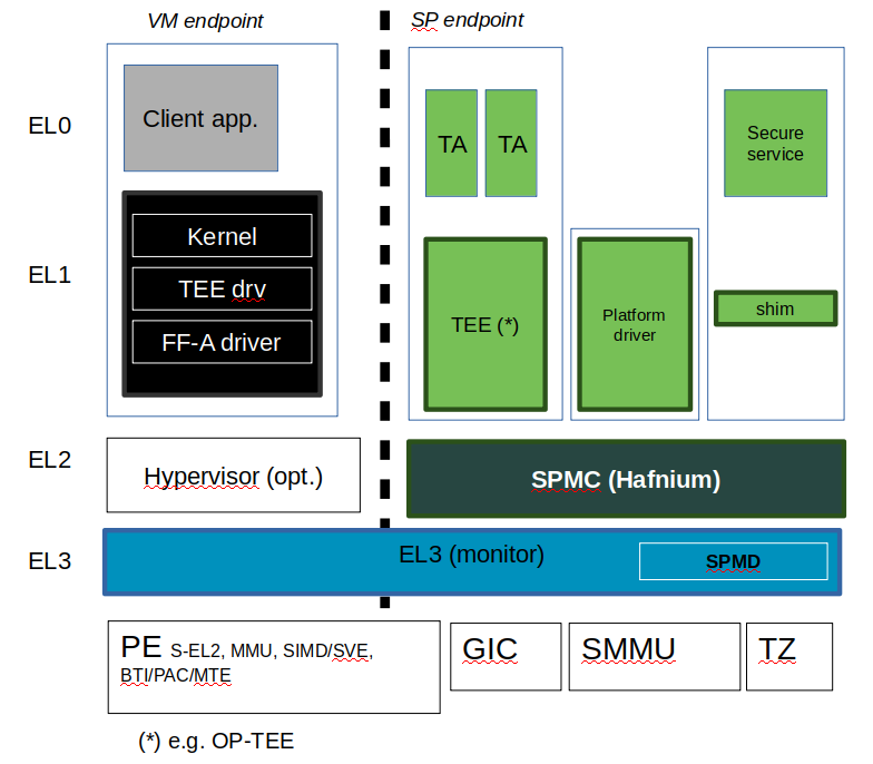
The following diagram illustrates a possible configuration when the FEAT_SEL2 architecture extension is implemented, showing the SPMD and SPMC, one or multiple secure partitions, with an optional Hypervisor:
12.4. TF-A build options
This section explains the TF-A build options involved in building with support for an FF-A based SPM where the SPMD is located at EL3 and the SPMC located at S-EL1 or S-EL2:
SPD=spmd: this option selects the SPMD component to relay the FF-A protocol from NWd to SWd back and forth. It is not possible to enable another Secure Payload Dispatcher when this option is chosen.
SPMD_SPM_AT_SEL2: this option adjusts the SPMC exception level to being S-EL1 or S-EL2. It defaults to enabled (value 1) when SPD=spmd is chosen.
CTX_INCLUDE_EL2_REGS: this option permits saving (resp. restoring) the EL2 system register context before entering (resp. after leaving) the SPMC. It is mandatorily enabled when
SPMD_SPM_AT_SEL2is enabled. The context save/restore routine and exhaustive list of registers is visible at [4].SP_LAYOUT_FILE: this option specifies a text description file providing paths to SP binary images and manifests in DTS format (see Describing secure partitions). It is required when
SPMD_SPM_AT_SEL2is enabled hence when multiple secure partitions are to be loaded on behalf of the SPMC.
CTX_INCLUDE_EL2_REGS |
SPMD_SPM_AT_SEL2 |
|
SPMC at S-EL1 |
0 |
0 |
SPMC at S-EL2 |
1 |
|
Other combinations of such build options either break the build or are not supported.
Notes:
Only Arm’s FVP platform is supported to use with the TF-A reference software stack.
The reference software stack uses FEAT_PAuth (formerly Armv8.3-PAuth) and FEAT_BTI (formerly Armv8.5-BTI) architecture extensions by default at EL3 and S-EL2.
The
CTX_INCLUDE_EL2_REGSoption provides the generic support for barely saving/restoring EL2 registers from an Arm arch perspective. As such it is decoupled from theSPD=spmdoption.BL32 option is re-purposed to specify the SPMC image. It can specify either the Hafnium binary path (built for the secure world) or the path to a TEE binary implementing FF-A interfaces.
BL33 option can specify the TFTF binary or a normal world loader such as U-Boot or the UEFI framework.
Sample TF-A build command line when SPMC is located at S-EL1 (e.g. when the FEAT_EL2 architecture extension is not implemented):
make \
CROSS_COMPILE=aarch64-none-elf- \
SPD=spmd \
SPMD_SPM_AT_SEL2=0 \
BL32=<path-to-tee-binary> \
BL33=<path-to-bl33-binary> \
PLAT=fvp \
all fip
Sample TF-A build command line for a FEAT_SEL2 enabled system where the SPMC is located at S-EL2:
make \
CROSS_COMPILE=aarch64-none-elf- \
PLAT=fvp \
SPD=spmd \
CTX_INCLUDE_EL2_REGS=1 \
ARM_ARCH_MINOR=5 \
BRANCH_PROTECTION=1 \
CTX_INCLUDE_PAUTH_REGS=1 \
BL32=<path-to-hafnium-binary> \
BL33=<path-to-bl33-binary> \
SP_LAYOUT_FILE=sp_layout.json \
all fip
Same as above with enabling secure boot in addition:
make \
CROSS_COMPILE=aarch64-none-elf- \
PLAT=fvp \
SPD=spmd \
CTX_INCLUDE_EL2_REGS=1 \
ARM_ARCH_MINOR=5 \
BRANCH_PROTECTION=1 \
CTX_INCLUDE_PAUTH_REGS=1 \
BL32=<path-to-hafnium-binary> \
BL33=<path-to-bl33-binary> \
SP_LAYOUT_FILE=sp_layout.json \
MBEDTLS_DIR=<path-to-mbedtls-lib> \
TRUSTED_BOARD_BOOT=1 \
COT=dualroot \
ARM_ROTPK_LOCATION=devel_rsa \
ROT_KEY=plat/arm/board/common/rotpk/arm_rotprivk_rsa.pem \
GENERATE_COT=1 \
all fip
12.5. FVP model invocation
The FVP command line needs the following options to exercise the S-EL2 SPMC:
|
Implements FEAT_SEL2, FEAT_PAuth, and FEAT_BTI. |
|
Parameters required for the SMMUv3.2 modeling. |
|
Implements FEAT_BTI. |
|
Required by the EL2 context save/restore routine. |
Sample FVP command line invocation:
<path-to-fvp-model>/FVP_Base_RevC-2xAEMv8A -C pctl.startup=0.0.0.0
-C cluster0.NUM_CORES=4 -C cluster1.NUM_CORES=4 -C bp.secure_memory=1 \
-C bp.secureflashloader.fname=trusted-firmware-a/build/fvp/debug/bl1.bin \
-C bp.flashloader0.fname=trusted-firmware-a/build/fvp/debug/fip.bin \
-C bp.pl011_uart0.out_file=fvp-uart0.log -C bp.pl011_uart1.out_file=fvp-uart1.log \
-C bp.pl011_uart2.out_file=fvp-uart2.log \
-C cluster0.has_arm_v8-5=1 -C cluster1.has_arm_v8-5=1 -C pci.pci_smmuv3.mmu.SMMU_AIDR=2 \
-C pci.pci_smmuv3.mmu.SMMU_IDR0=0x0046123B -C pci.pci_smmuv3.mmu.SMMU_IDR1=0x00600002 \
-C pci.pci_smmuv3.mmu.SMMU_IDR3=0x1714 -C pci.pci_smmuv3.mmu.SMMU_IDR5=0xFFFF0472 \
-C pci.pci_smmuv3.mmu.SMMU_S_IDR1=0xA0000002 -C pci.pci_smmuv3.mmu.SMMU_S_IDR2=0 \
-C pci.pci_smmuv3.mmu.SMMU_S_IDR3=0 \
-C cluster0.has_branch_target_exception=1 \
-C cluster1.has_branch_target_exception=1 \
-C cluster0.restriction_on_speculative_execution=2 \
-C cluster1.restriction_on_speculative_execution=2
12.6. Boot process
12.6.1. Loading Hafnium and secure partitions in the secure world
TF-A BL2 is the bootlader for the SPMC and SPs in the secure world.
SPs may be signed by different parties (SiP, OEM/ODM, TOS vendor, etc.). Thus they are supplied as distinct signed entities within the FIP flash image. The FIP image itself is not signed hence this provides the ability to upgrade SPs in the field.
12.6.2. Booting through TF-A
12.6.2.1. SP manifests
An SP manifest describes SP attributes as defined in [1] (partition manifest at virtual FF-A instance) in DTS format. It is represented as a single file associated with the SP. A sample is provided by [5]. A binding document is provided by [6].
12.6.2.2. Secure Partition packages
Secure partitions are bundled as independent package files consisting of:
a header
a DTB
an image payload
The header starts with a magic value and offset values to SP DTB and image payload. Each SP package is loaded independently by BL2 loader and verified for authenticity and integrity.
The SP package identified by its UUID (matching FF-A uuid property) is inserted as a single entry into the FIP at end of the TF-A build flow as shown:
Trusted Boot Firmware BL2: offset=0x1F0, size=0x8AE1, cmdline="--tb-fw"
EL3 Runtime Firmware BL31: offset=0x8CD1, size=0x13000, cmdline="--soc-fw"
Secure Payload BL32 (Trusted OS): offset=0x1BCD1, size=0x15270, cmdline="--tos-fw"
Non-Trusted Firmware BL33: offset=0x30F41, size=0x92E0, cmdline="--nt-fw"
HW_CONFIG: offset=0x3A221, size=0x2348, cmdline="--hw-config"
TB_FW_CONFIG: offset=0x3C569, size=0x37A, cmdline="--tb-fw-config"
SOC_FW_CONFIG: offset=0x3C8E3, size=0x48, cmdline="--soc-fw-config"
TOS_FW_CONFIG: offset=0x3C92B, size=0x427, cmdline="--tos-fw-config"
NT_FW_CONFIG: offset=0x3CD52, size=0x48, cmdline="--nt-fw-config"
B4B5671E-4A90-4FE1-B81F-FB13DAE1DACB: offset=0x3CD9A, size=0xC168, cmdline="--blob"
D1582309-F023-47B9-827C-4464F5578FC8: offset=0x48F02, size=0xC168, cmdline="--blob"
![/'
' Copyright (c) 2020, ARM Limited and Contributors. All rights reserved.
'
' SPDX-License-Identifier: BSD-3-Clause
'/
@startuml
folder SP_vendor_1 {
artifact sp_binary_1
artifact sp_manifest_1 [
sp_manifest_1
===
UUID = xxx
load_address = 0xaaa
owner = "Sip"
...
]
}
folder SP_vendor_2 {
artifact sp_binary_2
artifact sp_manifest_2 [
sp_manifest_2
===
UUID = yyy
load_address = 0xbbb
owner = "Plat"
]
}
artifact tb_fw_config.dts [
tb_fw_config.dts
----
secure-partitions
===
spkg_1 UUID
spkg_1 load_address
---
spkg_2 UUID
spkg_2 load_address
---
...
===
...<rest of the nodes>
]
artifact config.json [
SP_LAYOUT.json
===
path to sp_binary_1
path to sp_manifest_1
---
path to sp_binary_2
path to sp_manifest_2
---
...
]
control sp_mk_generator
artifact sp_gen [
sp_gen.mk
===
FDT_SOURCE = ...
SPTOOL_ARGS = ...
FIP_ARGS = ...
CRT_ARGS = ...
]
control dtc
control sptool
artifact tb_fw_config.dtb
artifact spkg_1 [
sp1.pkg
===
<i>header</i>
---
manifest
---
binary
]
artifact spkg_2 [
sp2.pkg
===
<i>header</i>
---
manifest
---
binary
]
artifact signed_tb_fw_config.dtb [
tb_fw_config.dtb (signed)
]
artifact signed_spkg_1 [
sp1.pkg (signed)
===
<i>header</i>
---
manifest
---
binary
---
<i>signature</I>
]
artifact signed_spkg_2 [
sp2.pkg (signed)
===
<i>header</i>
---
manifest
---
binary
---
<i>signature</I>
]
control crttool
control fiptool
artifact fip [
fip.bin
===
tb_fw_config.dtb (signed)
---
...
---
sp1.pkg (signed & SiP owned)
---
sp2.pkg (signed & Platform owned)
---
...
]
config.json .up.> SP_vendor_1
config.json .up.> SP_vendor_2
config.json --> sp_mk_generator
sp_mk_generator --> sp_gen
sp_gen --> fiptool
sp_gen --> cert_create
sp_gen --> sptool
sptool --> spkg_1
sptool --> spkg_2
spkg_1 --> cert_create
spkg_2 --> cert_create
cert_create --> signed_spkg_1
cert_create --> signed_spkg_2
tb_fw_config.dts --> dtc
dtc --> tb_fw_config.dtb
tb_fw_config.dtb --> cert_create
cert_create --> signed_tb_fw_config.dtb
signed_tb_fw_config.dtb --> fiptool
signed_spkg_1 -down-> fiptool
signed_spkg_2 -down-> fiptool
fiptool -down-> fip
@enduml](../_images/plantuml-f70df9f5081dcc645e5893ba3fa1ccc257e6cade.svg)
12.6.2.3. Describing secure partitions
A json-formatted description file is passed to the build flow specifying paths to the SP binary image and associated DTS partition manifest file. The latter is processed by the dtc compiler to generate a DTB fed into the SP package. This file also specifies the SP owner (as an optional field) identifying the signing domain in case of dual root CoT. The SP owner can either be the silicon or the platform provider. The corresponding “owner” field value can either take the value of “SiP” or “Plat”. In absence of “owner” field, it defaults to “SiP” owner.
{
    "tee1" : {
        "image": "tee1.bin",
         "pm": "tee1.dts",
         "owner": "SiP"
    },

    "tee2" : {
        "image": "tee2.bin",
        "pm": "tee2.dts",
        "owner": "Plat"
    }
}
12.6.2.4. SPMC manifest
This manifest contains the SPMC attribute node consumed by the SPMD at boot time. It implements [1] (SP manifest at physical FF-A instance) and serves two different cases:
The SPMC resides at S-EL1: the SPMC manifest is used by the SPMD to setup a SP that co-resides with the SPMC and executes at S-EL1 or Secure Supervisor mode.
The SPMC resides at S-EL2: the SPMC manifest is used by the SPMD to setup the environment required by the SPMC to run at S-EL2. SPs run at S-EL1 or S-EL0.
attribute {
    spmc_id = <0x8000>;
    maj_ver = <0x1>;
    min_ver = <0x0>;
    exec_state = <0x0>;
    load_address = <0x0 0x6000000>;
    entrypoint = <0x0 0x6000000>;
    binary_size = <0x60000>;
};
spmc_id defines the endpoint ID value that SPMC can query through
FFA_ID_GET.maj_ver/min_ver. SPMD checks provided version versus its internal version and aborts if not matching.
exec_state defines the SPMC execution state (AArch64 or AArch32). Notice Hafnium used as a SPMC only supports AArch64.
load_address and binary_size are mostly used to verify secondary entry points fit into the loaded binary image.
entrypoint defines the cold boot primary core entry point used by SPMD (currently matches
BL32_BASE) to enter the SPMC.
Other nodes in the manifest are consumed by Hafnium in the secure world. A sample can be found at [7]:
The hypervisor node describes SPs. is_ffa_partition boolean attribute indicates a FF-A compliant SP. The load_address field specifies the load address at which TF-A loaded the SP package.
cpus node provide the platform topology and allows MPIDR to VMPIDR mapping. Note the primary core is declared first, then secondary core are declared in reverse order.
The memory node provides platform information on the ranges of memory available to the SPMC.
12.6.2.5. SPMC boot
The SPMC is loaded by BL2 as the BL32 image.
The SPMC manifest is loaded by BL2 as the TOS_FW_CONFIG image.
BL2 passes the SPMC manifest address to BL31 through a register.
At boot time, the SPMD in BL31 runs from the primary core, initializes the core contexts and launches the SPMC (BL32) passing the SPMC manifest address through a register.
12.6.2.6. Loading of SPs
At boot time, BL2 loads SPs sequentially in addition to the SPMC as depicted below:

Note this boot flow is an implementation sample on Arm’s FVP platform. Platforms not using TF-A’s Firmware CONFiguration framework would adjust to a different implementation.
12.6.2.7. Secure boot
The SP content certificate is inserted as a separate FIP item so that BL2 loads SPMC, SPMC manifest, secure partitions and verifies them for authenticity and integrity. Refer to TBBR specification [3].
The multiple-signing domain feature (in current state dual signing domain [8]) allows the use of two root keys namely S-ROTPK and NS-ROTPK:
SPMC (BL32) and SPMC manifest are signed by the SiP using the S-ROTPK.
BL33 may be signed by the OEM using NS-ROTPK.
An SP may be signed either by SiP (using S-ROTPK) or by OEM (using NS-ROTPK).
Also refer to Describing secure partitions and TF-A build options sections.
12.7. Hafnium in the secure world
12.7.1. General considerations
12.7.1.1. Build platform for the secure world
In the Hafnium reference implementation specific code parts are only relevant to
the secure world. Such portions are isolated in architecture specific files
and/or enclosed by a SECURE_WORLD macro.
12.7.1.2. Secure partitions CPU scheduling
The FF-A v1.0 specification [1] provides two ways to relinquinsh CPU time to secure partitions. For this a VM (Hypervisor or OS kernel), or SP invokes one of:
the FFA_MSG_SEND_DIRECT_REQ interface.
the FFA_RUN interface.
12.7.1.3. Platform topology
The execution-ctx-count SP manifest field can take the value of one or the total number of PEs. The FF-A v1.0 specification [1] recommends the following SP types:
Pinned MP SPs: an execution context matches a physical PE. MP SPs must implement the same number of ECs as the number of PEs in the platform.
Migratable UP SPs: a single execution context can run and be migrated on any physical PE. Such SP declares a single EC in its SP manifest. An UP SP can receive a direct message request originating from any physical core targeting the single execution context.
12.7.2. Parsing SP partition manifests
Hafnium consumes SP manifests as defined in [1] and SP manifests. Note the current implementation may not implement all optional fields.
The SP manifest may contain memory and device regions nodes. In case of an S-EL2 SPMC:
Memory regions are mapped in the SP EL1&0 Stage-2 translation regime at load time (or EL1&0 Stage-1 for an S-EL1 SPMC). A memory region node can specify RX/TX buffer regions in which case it is not necessary for an SP to explicitly invoke the
FFA_RXTX_MAPinterface.Device regions are mapped in the SP EL1&0 Stage-2 translation regime (or EL1&0 Stage-1 for an S-EL1 SPMC) as peripherals and possibly allocate additional resources (e.g. interrupts).
For the S-EL2 SPMC, base addresses for memory and device region nodes are IPAs provided the SPMC identity maps IPAs to PAs within SP EL1&0 Stage-2 translation regime.
Note: in the current implementation both VTTBR_EL2 and VSTTBR_EL2 point to the same set of page tables. It is still open whether two sets of page tables shall be provided per SP. The memory region node as defined in the specification provides a memory security attribute hinting to map either to the secure or non-secure EL1&0 Stage-2 table if it exists.
12.7.3. Passing boot data to the SP
In [1] , the “Protocol for passing data” section defines a method for passing boot data to SPs (not currently implemented).
Provided that the whole secure partition package image (see Secure Partition packages) is mapped to the SP secure EL1&0 Stage-2 translation regime, an SP can access its own manifest DTB blob and extract its partition manifest properties.
12.7.4. SP Boot order
SP manifests provide an optional boot order attribute meant to resolve dependencies such as an SP providing a service required to properly boot another SP.
It is possible for an SP to call into another SP through a direct request provided the latter SP has already been booted.
12.7.5. Boot phases
12.7.5.1. Primary core boot-up
Upon boot-up, BL31 hands over to the SPMC (BL32) on the primary boot physical core. The SPMC performs its platform initializations and registers the SPMC secondary physical core entry point physical address by the use of the FFA_SECONDARY_EP_REGISTER interface (SMC invocation from the SPMC to the SPMD at secure physical FF-A instance). This interface is implementation-defined in context of FF-A v1.0.
The SPMC then creates secure partitions based on SP packages and manifests. Each secure partition is launched in sequence (SP Boot order) on their “primary” execution context. If the primary boot physical core linear id is N, an MP SP is started using EC[N] on PE[N] (see Platform topology). If the partition is a UP SP, it is started using its unique EC0 on PE[N].
The SP primary EC (or the EC used when the partition is booted as described above):
Performs the overall SP boot time initialization, and in case of a MP SP, prepares the SP environment for other execution contexts.
In the case of a MP SP, it invokes the FFA_SECONDARY_EP_REGISTER at secure virtual FF-A instance (SMC invocation from SP to SPMC) to provide the IPA entry point for other execution contexts.
Exits through
FFA_MSG_WAITto indicate successful initialization orFFA_ERRORin case of failure.
12.7.5.2. Secondary cores boot-up
Once the system is started and NWd brought up, a secondary physical core is
woken up by the PSCI_CPU_ON service invocation. The TF-A SPD hook mechanism
calls into the SPMD on the newly woken up physical core. Then the SPMC is
entered at the secondary physical core entry point.
In the current implementation, the first SP is resumed on the coresponding EC (the virtual CPU which matches the physical core). The implication is that the first SP must be a MP SP.
In a linux based system, once secure and normal worlds are booted but prior to a NWd FF-A driver has been loaded:
The first SP has initialized all its ECs in response to primary core boot up (at system initialization) and secondary core boot up (as a result of linux invoking PSCI_CPU_ON for all secondary cores).
Other SPs have their first execution context initialized as a result of secure world initialization on the primary boot core. Other ECs for those SPs have to be run first through ffa_run to complete their initialization (which results in the EC completing with FFA_MSG_WAIT).
Refer to Power management for further details.
12.7.6. Mandatory interfaces
The following interfaces are exposed to SPs:
FFA_VERSIONFFA_FEATURESFFA_RX_RELEASEFFA_RXTX_MAPFFA_RXTX_UNMAP(not implemented)FFA_PARTITION_INFO_GETFFA_ID_GETFFA_MSG_WAITFFA_MSG_SEND_DIRECT_REQFFA_MSG_SEND_DIRECT_RESPFFA_MEM_DONATEFFA_MEM_LENDFFA_MEM_SHAREFFA_MEM_RETRIEVE_REQFFA_MEM_RETRIEVE_RESPFFA_MEM_RELINQUISHFFA_MEM_RECLAIMFFA_SECONDARY_EP_REGISTER
12.7.6.1. FFA_VERSION
FFA_VERSION requires a requested_version parameter from the caller.
The returned value depends on the caller:
Hypervisor or OS kernel in NS-EL1/EL2: the SPMD returns the SPMC version specified in the SPMC manifest.
SP: the SPMC returns its own implemented version.
SPMC at S-EL1/S-EL2: the SPMD returns its own implemented version.
12.7.6.2. FFA_FEATURES
FF-A features supported by the SPMC may be discovered by secure partitions at boot (that is prior to NWd is booted) or run-time.
The SPMC calling FFA_FEATURES at secure physical FF-A instance always get FFA_SUCCESS from the SPMD.
The request made by an Hypervisor or OS kernel is forwarded to the SPMC and the response relayed back to the NWd.
12.7.6.3. FFA_RXTX_MAP/FFA_RXTX_UNMAP
When invoked from a secure partition FFA_RXTX_MAP maps the provided send and receive buffers described by their IPAs to the SP EL1&0 Stage-2 translation regime as secure buffers in the MMU descriptors.
When invoked from the Hypervisor or OS kernel, the buffers are mapped into the SPMC EL2 Stage-1 translation regime and marked as NS buffers in the MMU descriptors.
Note:
FFA_RXTX_UNMAP is not implemented.
12.7.6.4. FFA_PARTITION_INFO_GET
Partition info get call can originate:
from SP to SPMC
from Hypervisor or OS kernel to SPMC. The request is relayed by the SPMD.
12.7.6.5. FFA_ID_GET
The FF-A id space is split into a non-secure space and secure space:
FF-A ID with bit 15 clear relates to VMs.
FF-A ID with bit 15 set related to SPs.
FF-A IDs 0, 0xffff, 0x8000 are assigned respectively to the Hypervisor, SPMD and SPMC.
The SPMD returns:
The default zero value on invocation from the Hypervisor.
The
spmc_idvalue specified in the SPMC manifest on invocation from the SPMC (see SPMC manifest)
This convention helps the SPMC to determine the origin and destination worlds in an FF-A ABI invocation. In particular the SPMC shall filter unauthorized transactions in its world switch routine. It must not be permitted for a VM to use a secure FF-A ID as origin world by spoofing:
A VM-to-SP direct request/response shall set the origin world to be non-secure (FF-A ID bit 15 clear) and destination world to be secure (FF-A ID bit 15 set).
Similarly, an SP-to-SP direct request/response shall set the FF-A ID bit 15 for both origin and destination IDs.
An incoming direct message request arriving at SPMD from NWd is forwarded to SPMC without a specific check. The SPMC is resumed through eret and “knows” the message is coming from normal world in this specific code path. Thus the origin endpoint ID must be checked by SPMC for being a normal world ID.
An SP sending a direct message request must have bit 15 set in its origin endpoint ID and this can be checked by the SPMC when the SP invokes the ABI.
The SPMC shall reject the direct message if the claimed world in origin endpoint ID is not consistent:
It is either forwarded by SPMD and thus origin endpoint ID must be a “normal world ID”,
or initiated by an SP and thus origin endpoint ID must be a “secure world ID”.
12.7.6.6. FFA_MSG_SEND_DIRECT_REQ/FFA_MSG_SEND_DIRECT_RESP
This is a mandatory interface for secure partitions consisting in direct request and responses with the following rules:
An SP can send a direct request to another SP.
An SP can receive a direct request from another SP.
An SP can send a direct response to another SP.
An SP cannot send a direct request to an Hypervisor or OS kernel.
An Hypervisor or OS kernel can send a direct request to an SP.
An SP can send a direct response to an Hypervisor or OS kernel.
12.7.7. SPMC-SPMD direct requests/responses
Implementation-defined FF-A IDs are allocated to the SPMC and SPMD. Using those IDs in source/destination fields of a direct request/response permits SPMD to SPMC communication and either way.
SPMC to SPMD direct request/response uses SMC conduit.
SPMD to SPMC direct request/response uses ERET conduit.
12.7.8. PE MMU configuration
With secure virtualization enabled, two IPA spaces are output from the secure EL1&0 Stage-1 translation (secure and non-secure). The EL1&0 Stage-2 translation hardware is fed by:
A single secure IPA space when the SP EL1&0 Stage-1 MMU is disabled.
Two IPA spaces (secure and non-secure) when the SP EL1&0 Stage-1 MMU is enabled.
VTCR_EL2 and VSTCR_EL2 provide configuration bits for controlling the
NS/S IPA translations.
VSTCR_EL2.SW = 0, VSTCR_EL2.SA = 0,``VTCR_EL2.NSW`` = 0, VTCR_EL2.NSA = 1:
Stage-2 translations for the NS IPA space access the NS PA space.
Stage-2 translation table walks for the NS IPA space are to the secure PA space.
Secure and non-secure IPA regions use the same set of Stage-2 page tables within a SP.
12.7.9. Interrupt management
12.7.9.1. GIC ownership
The SPMC owns the GIC configuration. Secure and non-secure interrupts are trapped at S-EL2. The SPMC manages interrupt resources and allocates interrupt IDs based on SP manifests. The SPMC acknowledges physical interrupts and injects virtual interrupts by setting the use of vIRQ/vFIQ bits before resuming a SP.
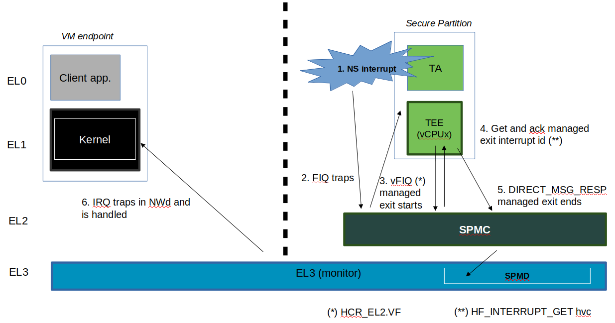
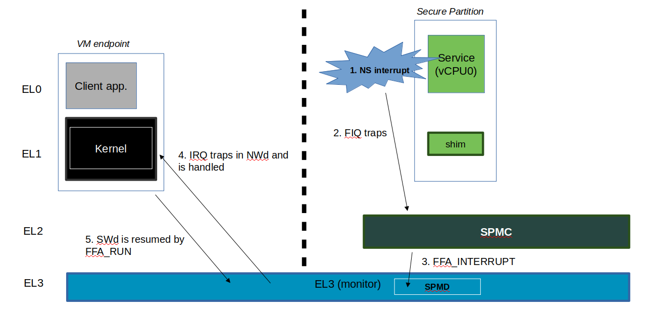
12.7.9.2. Non-secure interrupt handling
The following illustrate the scenarios of non secure physical interrupts trapped by the SPMC:
The SP handles a managed exit operation:
The SP is pre-empted without managed exit:
12.7.9.3. Secure interrupt handling
The current implementation does not support handling of secure interrupts trapped by the SPMC at S-EL2. This is work in progress planned for future releases.
12.7.10. Power management
In platforms with or without secure virtualization:
The NWd owns the platform PM policy.
The Hypervisor or OS kernel is the component initiating PSCI service calls.
The EL3 PSCI library is in charge of the PM coordination and control (eventually writing to platform registers).
While coordinating PM events, the PSCI library calls backs into the Secure Payload Dispatcher for events the latter has statically registered to.
When using the SPMD as a Secure Payload Dispatcher:
A power management event is relayed through the SPD hook to the SPMC.
In the current implementation only cpu on (svc_on_finish) and cpu off (svc_off) hooks are registered.
The behavior for the cpu on event is described in Secondary cores boot-up. The SPMC is entered through its secondary physical core entry point.
The cpu off event occurs when the NWd calls PSCI_CPU_OFF. The method by which the PM event is conveyed to the SPMC is implementation-defined in context of FF-A v1.0 (SPMC-SPMD direct requests/responses). It consists in a SPMD-to-SPMC direct request/response conveying the PM event details and SPMC response. The SPMD performs a synchronous entry into the SPMC. The SPMC is entered and updates its internal state to reflect the physical core is being turned off. In the current implementation no SP is resumed as a consequence. This behavior ensures a minimal support for CPU hotplug e.g. when initiated by the NWd linux userspace.
12.8. SMMUv3 support in Hafnium
An SMMU is analogous to an MMU in a CPU. It performs address translations for Direct Memory Access (DMA) requests from system I/O devices. The responsibilities of an SMMU include:
Translation: Incoming DMA requests are translated from bus address space to system physical address space using translation tables compliant to Armv8/Armv7 VMSA descriptor format.
Protection: An I/O device can be prohibited from read, write access to a memory region or allowed.
Isolation: Traffic from each individial device can be independently managed. The devices are differentiated from each other using unique translation tables.
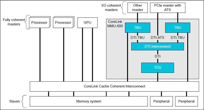
The following diagram illustrates a typical SMMU IP integrated in a SoC with several I/O devices along with Interconnect and Memory system.
SMMU has several versions including SMMUv1, SMMUv2 and SMMUv3. Hafnium provides support for SMMUv3 driver in both normal and secure world. A brief introduction of SMMUv3 functionality and the corresponding software support in Hafnium is provided here.
12.8.1. SMMUv3 features
SMMUv3 provides Stage1, Stage2 translation as well as nested (Stage1 + Stage2) translation support. It can either bypass or abort incoming translations as well.
Traffic (memory transactions) from each upstream I/O peripheral device, referred to as Stream, can be independently managed using a combination of several memory based configuration structures. This allows the SMMUv3 to support a large number of streams with each stream assigned to a unique translation context.
Support for Armv8.1 VMSA where the SMMU shares the translation tables with a Processing Element. AArch32(LPAE) and AArch64 translation table format are supported by SMMUv3.
SMMUv3 offers non-secure stream support with secure stream support being optional. Logically, SMMUv3 behaves as if there is an indepdendent SMMU instance for secure and non-secure stream support.
It also supports sub-streams to differentiate traffic from a virtualized peripheral associated with a VM/SP.
Additionally, SMMUv3.2 provides support for PEs implementing Armv8.4-A extensions. Consequently, SPM depends on Secure EL2 support in SMMUv3.2 for providing Secure Stage2 translation support to upstream peripheral devices.
12.8.2. SMMUv3 Programming Interfaces
SMMUv3 has three software interfaces that are used by the Hafnium driver to configure the behaviour of SMMUv3 and manage the streams.
Memory based data strutures that provide unique translation context for each stream.
Memory based circular buffers for command queue and event queue.
A large number of SMMU configuration registers that are memory mapped during boot time by Hafnium driver. Except a few registers, all configuration registers have independent secure and non-secure versions to configure the behaviour of SMMUv3 for translation of secure and non-secure streams respectively.
12.8.3. Peripheral device manifest
Currently, SMMUv3 driver in Hafnium only supports dependent peripheral devices. These devices are dependent on PE endpoint to initiate and receive memory management transactions on their behalf. The acccess to the MMIO regions of any such device is assigned to the endpoint during boot. Moreover, SMMUv3 driver uses the same stage 2 translations for the device as those used by partition manager on behalf of the PE endpoint. This ensures that the peripheral device has the same visibility of the physical address space as the endpoint. The device node of the corresponding partition manifest (refer to [1] section 3.2 ) must specify these additional properties for each peripheral device in the system :
smmu-id: This field helps to identify the SMMU instance that this device is upstream of.
stream-ids: List of stream IDs assigned to this device.
smmuv3-testengine {
    base-address = <0x00000000 0x2bfe0000>;
    pages-count = <32>;
    attributes = <0x3>;
    smmu-id = <0>;
    stream-ids = <0x0 0x1>;
    interrupts = <0x2 0x3>, <0x4 0x5>;
    exclusive-access;
};
12.8.4. SMMUv3 driver limitations
The primary design goal for the Hafnium SMMU driver is to support secure streams.
Currently, the driver only supports Stage2 translations. No support for Stage1 or nested translations.
Supports only AArch64 translation format.
No support for features such as PCI Express (PASIDs, ATS, PRI), MSI, RAS, Fault handling, Performance Monitor Extensions, Event Handling, MPAM.
No support for independent peripheral devices.
12.9. References
[1] Arm Firmware Framework for Armv8-A
[2] Secure Partition Manager using MM interface
[3] Trusted Boot Board Requirements Client
[5] https://git.trustedfirmware.org/TF-A/tf-a-tests.git/tree/spm/cactus/plat/arm/fvp/fdts/cactus.dts
[6] https://trustedfirmware-a.readthedocs.io/en/latest/components/ffa-manifest-binding.html
[8] https://lists.trustedfirmware.org/pipermail/tf-a/2020-February/000296.html
Copyright (c) 2020-2021, Arm Limited and Contributors. All rights reserved.