5.7. CPU Reset
This document describes the high-level design of the framework to handle CPU resets in Trusted Firmware-A (TF-A). It also describes how the platform integrator can tailor this code to the system configuration to some extent, resulting in a simplified and more optimised boot flow.
This document should be used in conjunction with the Firmware Design document which provides greater implementation details around the reset code, specifically for the cold boot path.
5.7.1. General reset code flow
The TF-A reset code is implemented in BL1 by default. The following high-level diagram illustrates this:
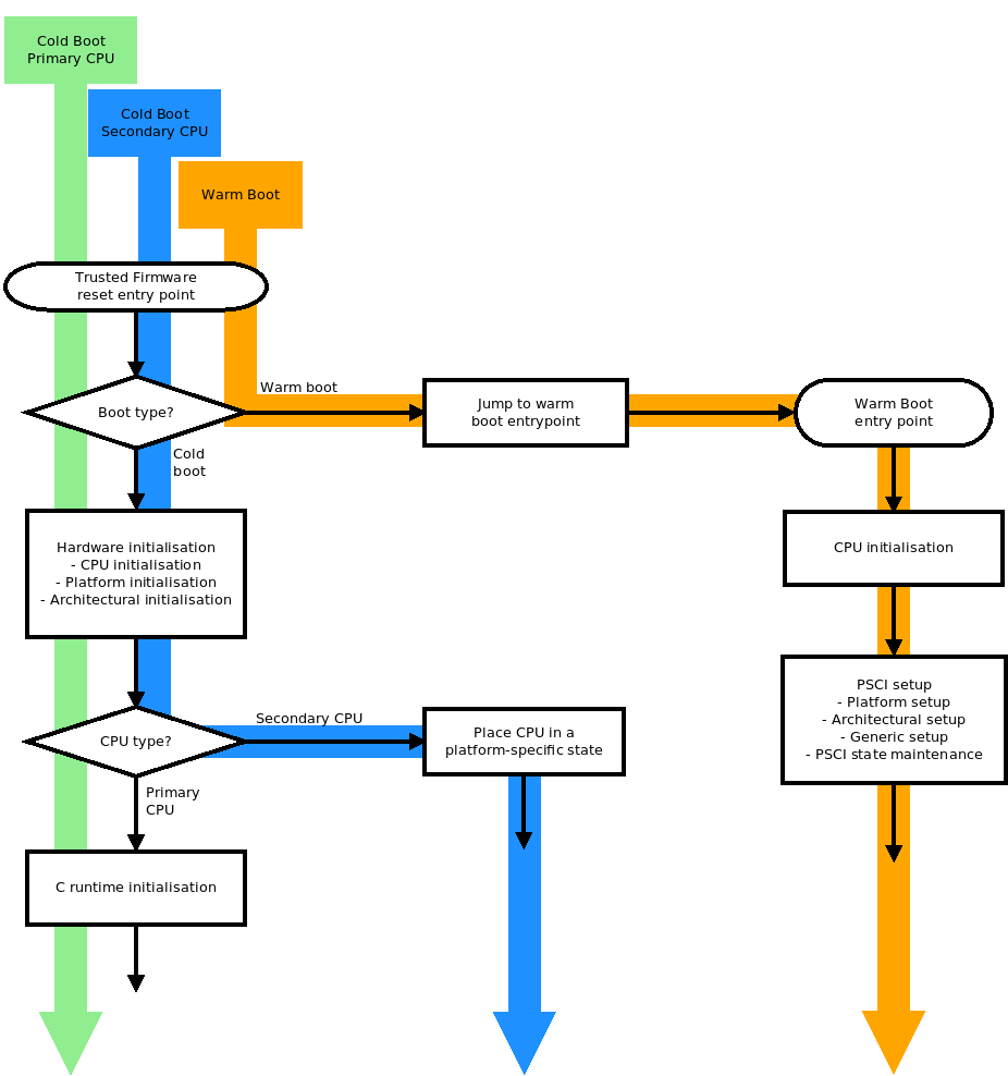
This diagram shows the default, unoptimised reset flow. Depending on the system configuration, some of these steps might be unnecessary. The following sections guide the platform integrator by indicating which build options exclude which steps, depending on the capability of the platform.
Note
If BL31 is used as the TF-A entry point instead of BL1, the diagram above is still relevant, as all these operations will occur in BL31 in this case. Please refer to section 6 “Using BL31 entrypoint as the reset address” for more information.
5.7.2. Programmable CPU reset address
By default, TF-A assumes that the CPU reset address is not programmable. Therefore, all CPUs start at the same address (typically address 0) whenever they reset. Further logic is then required to identify whether it is a cold or warm boot to direct CPUs to the right execution path.
If the reset vector address (reflected in the reset vector base address register
RVBAR_EL3) is programmable then it is possible to make each CPU start directly
at the right address, both on a cold and warm reset. Therefore, the boot type
detection can be skipped, resulting in the following boot flow:
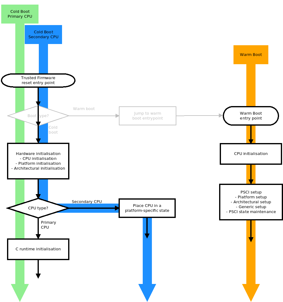
To enable this boot flow, compile TF-A with PROGRAMMABLE_RESET_ADDRESS=1.
This option only affects the TF-A reset image, which is BL1 by default or BL31 if
RESET_TO_BL31=1.
On both the FVP and Juno platforms, the reset vector address is not programmable
so both ports use PROGRAMMABLE_RESET_ADDRESS=0.
5.7.3. Cold boot on a single CPU
By default, TF-A assumes that several CPUs may be released out of reset. Therefore, the cold boot code has to arbitrate access to hardware resources shared amongst CPUs. This is done by nominating one of the CPUs as the primary, which is responsible for initialising shared hardware and coordinating the boot flow with the other CPUs.
If the platform guarantees that only a single CPU will ever be brought up then no arbitration is required. The notion of primary/secondary CPU itself no longer applies. This results in the following boot flow:
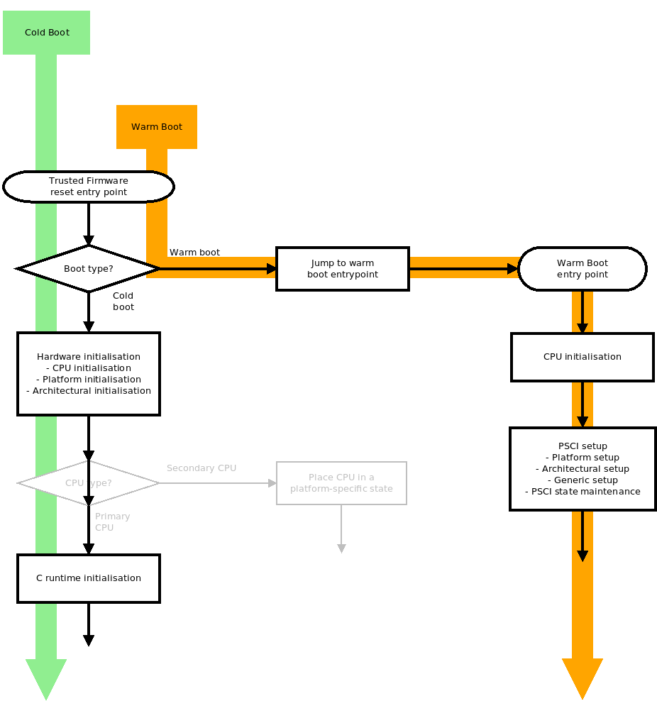
To enable this boot flow, compile TF-A with COLD_BOOT_SINGLE_CPU=1. This
option only affects the TF-A reset image, which is BL1 by default or BL31 if
RESET_TO_BL31=1.
On both the FVP and Juno platforms, although only one core is powered up by
default, there are platform-specific ways to release any number of cores out of
reset. Therefore, both platform ports use COLD_BOOT_SINGLE_CPU=0.
5.7.4. Programmable CPU reset address, Cold boot on a single CPU
It is obviously possible to combine both optimisations on platforms that have a programmable CPU reset address and which release a single CPU out of reset. This results in the following boot flow:
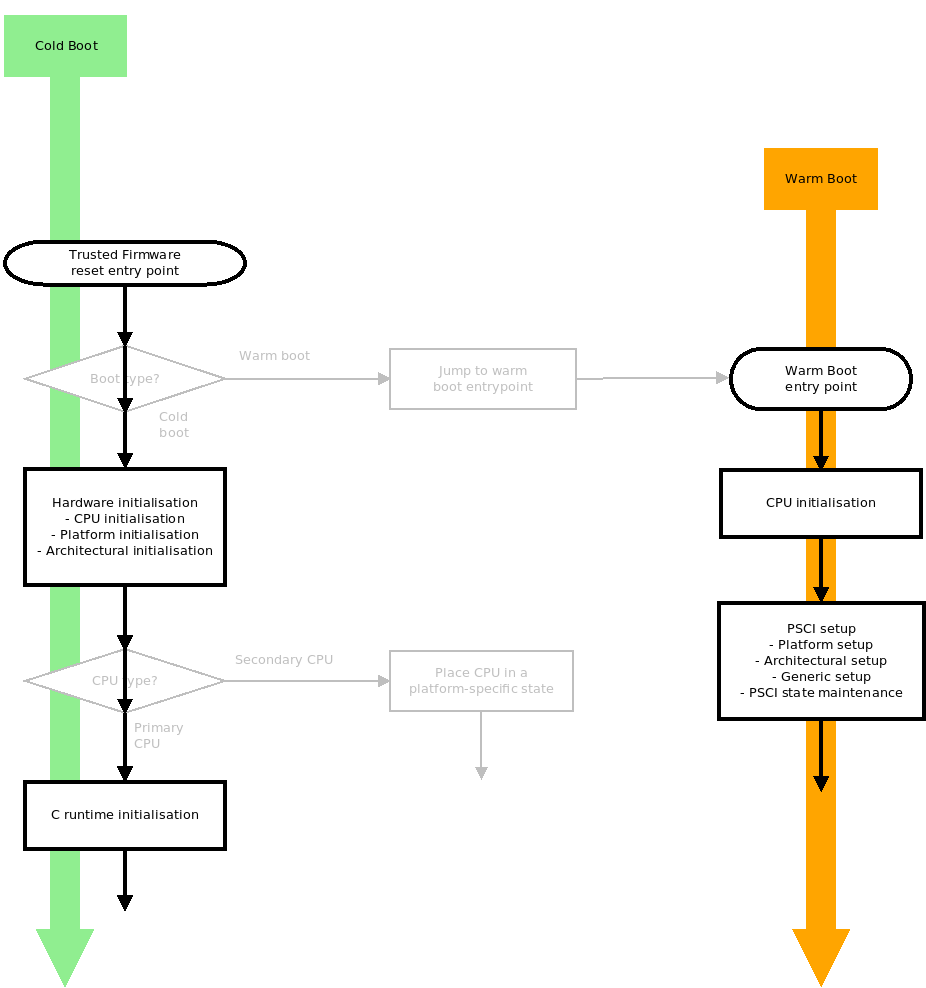
To enable this boot flow, compile TF-A with both COLD_BOOT_SINGLE_CPU=1
and PROGRAMMABLE_RESET_ADDRESS=1. These options only affect the TF-A reset
image, which is BL1 by default or BL31 if RESET_TO_BL31=1.
5.7.5. Using BL31 entrypoint as the reset address
On some platforms the runtime firmware (BL3x images) for the application processors are loaded by some firmware running on a secure system processor on the SoC, rather than by BL1 and BL2 running on the primary application processor. For this type of SoC it is desirable for the application processor to always reset to BL31 which eliminates the need for BL1 and BL2.
TF-A provides a build-time option RESET_TO_BL31 that includes some additional
logic in the BL31 entry point to support this use case.
In this configuration, the platform’s Trusted Boot Firmware must ensure that
BL31 is loaded to its runtime address, which must match the CPU’s RVBAR_EL3
reset vector base address, before the application processor is powered on.
Additionally, platform software is responsible for loading the other BL3x images
required and providing entry point information for them to BL31. Loading these
images might be done by the Trusted Boot Firmware or by platform code in BL31.
Although the Arm FVP platform does not support programming the reset base
address dynamically at run-time, it is possible to set the initial value of the
RVBAR_EL3 register at start-up. This feature is provided on the Base FVP
only.
It allows the Arm FVP port to support the RESET_TO_BL31 configuration, in
which case the bl31.bin image must be loaded to its run address in Trusted
SRAM and all CPU reset vectors be changed from the default 0x0 to this run
address. See the Arm Fixed Virtual Platforms (FVP) for details of running
the FVP models in this way.
Although technically it would be possible to program the reset base address with
the right support in the SCP firmware, this is currently not implemented so the
Juno port doesn’t support the RESET_TO_BL31 configuration.
The RESET_TO_BL31 configuration requires some additions and changes in the
BL31 functionality:
5.7.5.1. Determination of boot path
In this configuration, BL31 uses the same reset framework and code as the one
described for BL1 above. Therefore, it is affected by the
PROGRAMMABLE_RESET_ADDRESS and COLD_BOOT_SINGLE_CPU build options in the
same way.
In the default, unoptimised BL31 reset flow, on a warm boot a CPU is directed to the PSCI implementation via a platform defined mechanism. On a cold boot, the platform must place any secondary CPUs into a safe state while the primary CPU executes a modified BL31 initialization, as described below.
5.7.5.2. Platform initialization
In this configuration, since the CPU resets to BL31, no parameters are expected
to be passed to BL31 (see notes below for clarification).
Instead, the platform code in BL31 needs to know, or be able to determine, the
location of the BL32 (if required) and BL33 images and provide this information
in response to the bl31_plat_get_next_image_ep_info() function.
Additionally, platform software is responsible for carrying out any security initialisation, for example programming a TrustZone address space controller. This might be done by the Trusted Boot Firmware or by platform code in BL31.
Note
Even though RESET_TO_BL31 is designed such that BL31 is the reset BL image, some platforms may wish to pass some arguments to BL31 as per the defined contract between BL31 and previous bootloaders. Previous bootloaders can pass arguments through registers x0 through x3. BL31 will preserve them and propagate them to platform code, which will handle these arguments in an IMPDEF manner.
Copyright (c) 2015-2023, Arm Limited and Contributors. All rights reserved.